Temperature Measurement

In my PhD thesis I have demonstrated a very interesting feature of a temperature measurement system which uses a p-n junction as a temperature transducer. This characteristic consists of the fact that the maximum absolute error of such a system is directly proportional to the square of the temperature interval. Using this feature, the maximum theoretical error of a temperature measurement system which functions in the interval -20 oC … +120 oC is of 0.04 oC. All of the theoretical results have been validated by simulation.
A more detailed analysis is presented in a paper published in 1997 (Temperature Paper 1997.pdf).
A NEW ALGORITHM FOR A HIGHER PRECISION TEMPERATURE MEASUREMENT
-
1.INTRODUCTION
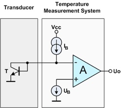
To design a temperature measurement system with a p-n junction as temperature transducer requires excitation (IB), offsetting (UB) and amplification (A). The conceptual block diagram of a temperature measurement system is shown in Figure 1.
Figure 1. Conceptual block diagram of a temperature measurement system.
The base-emitter voltage of the silicon bipolar junction transistor can be determinate in any conditions of collector current and temperature if its value (UBE0) is known, measured at a collector current (ICO) and temperature TO.
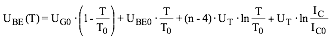
where UGO is the band-gap voltage of silicon extrapolated at zero degrees Kelvin, n is dependent on doping level in the base, UT is the thermal voltage evaluated at T and UBEO is the base - emitter voltage measured at ICO and TO.
-
2.ERROR ANALYSIS
The absolute error of the temperature measurement system defined as:
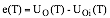
where UOI(T) is the linear (ideal) law of variation with temperature of this voltage, has the maximum value:

where c is a temperature independent constant and DT represents the temperature range (Tmax-Tmin).
-
3.ALGORITHM
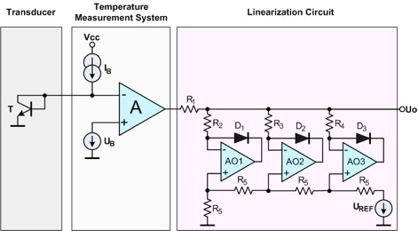
The square-law relationship is found to be an even closer approximation of the absolute error expression. Dividing the entire temperature range in 'm' sub-ranges, the maximum absolute error will decrease by m2. In Figure 2 is presented a hardware implementation of the algorithm for m=4 sub-ranges.
-
4.SIMULATION RESULTS
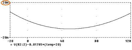
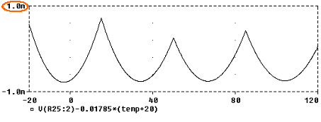
The absolute error variation law vs. temperature for the temperature measurement system output designed as in Figure 1 is shown in Figure 3. As a simulation result of the system shown in Figure 2, the absolute error is in the range of ± 0.71 mV and this means just ± 0.04 oC over the entire temperature range (Figure 4).
Figure 3. Absolute error variation law for a usual analog temperature measurement system.
Figure 4. Absolute error variation law for the proposed system.
-
5.CONCLUSION
Excellent linearity and simplicity make this algorithm useful in a variety of applications such as: precision temperature measurement, high-quality industrial process control, and biomedical equipment.
Figure 2. Conceptual block diagram of the high – precision temperature measurement system.